Bạn đang tìm kiếm cái gì?
A metal exhaust heat shield does not work in isolation. Its position relative to the hot component, the way it is mounted and the clearance available around its edges can be just as important as the sheet material itself.
For an OEM project, specifying only “stainless steel heat shield” or “aluminum heat shield” leaves several critical questions unanswered. Is the shield intended to stand away from the manifold or turbocharger? Where are the mounting points? Which component needs protection? How much installed space is available after the exhaust moves and expands?
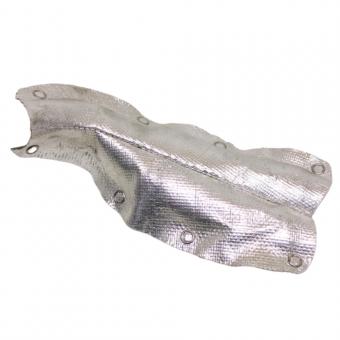
BSTFLEX manufactures rigid exhaust shielding including the Exhaust Manifold Heat Shield and Stamped Turbocharger Heat Shield. For custom projects, air gap and mounting details should be treated as part of the component specification rather than added after the shield shape has already been finalized.
The first drawing mark should not necessarily be the heat shield. Identify the part that must remain within an acceptable thermal condition.
Typical nearby components may include:
Mark the relationship between that component and the exhaust manifold, turbocharger or pipe. This establishes the direction of the thermal exposure and helps determine where the shield actually needs coverage.
A larger shield is not automatically a better shield. Increasing its area can interfere with service access, reduce ventilation, add weight or move the outer surface closer to another temperature-sensitive part. The required coverage should follow the thermal problem being solved.
An exhaust heat shield air gap is the separation between the hot component and a shield that is designed to stand away from it. That separation can help interrupt direct heat transfer and provides space between the exhaust surface and the outer barrier.
There is no single air-gap dimension that should be copied into every manifold, turbocharger or exhaust-pipe project. The appropriate spacing depends on the complete design, including:
The drawing should therefore show the required installed relationship rather than relying on an informal instruction such as “leave some space behind the shield.”
Where the customer already has a validated original design, preserve its critical spacing and mounting concept unless a revised configuration has been evaluated. Where BSTFLEX is quoting from a new drawing or sample, identify which clearances are fixed requirements and which can be reviewed during development.
A shield may have generous space at its center but almost touch the exhaust around a formed edge, mounting boss or bend. The nominal distance between two broad surfaces does not describe these local conditions.
For a drawing review, mark the critical sections and provide the minimum permitted clearance at those locations. Useful section views include:
Also distinguish between hot-side clearance and cold-side clearance. A shield can clear the exhaust correctly while still sitting too close to the component it is intended to protect.
Measurements taken on a stationary cold assembly are only one condition. Exhaust components, mounting brackets and neighboring structures can change position as temperatures rise or as the engine moves under operating loads.
For critical installations, the responsible engineering team should identify the movement that must be accommodated and the areas where contact is unacceptable. This may include thermal growth, engine movement, vibration or movement at adjoining exhaust connections.
Do not intentionally bend a production shield against the hot component simply to gain additional clearance elsewhere unless that change has been approved. The revised shape can alter the intended spacing, attachment load and thermal path.
A metal shield may stand away from the exhaust over most of its area while being connected through brackets, bolts or formed tabs. These attachment points create mechanical connections between parts of the assembly and must be considered in the thermal design.
This does not mean every mounting point requires an insulating spacer. It means the fastening arrangement should be evaluated as part of the system rather than treated as unrelated hardware.
For an exhaust heat shield mounting specification, identify:
| Mounting item | What should be defined |
|---|---|
| Mounting location | Reference surface, boss, bracket or approved attachment point |
| Hole or slot | Geometry, position and whether movement is intentionally permitted |
| Spacer or stand-off | Part number, dimensions and assembly position where applicable |
| Fastener | Specified type and the applicable assembly requirement |
| Shield tab | Formed geometry, orientation and clearance around adjoining parts |
| Service access | Space required to install and remove the fastener |
Do not invent a generic bolt torque, washer stack or stand-off height for a custom project. Those details belong to the approved assembly specification.
The formed tab is often where the flat sheet becomes a functional automotive part. Its angle, transition radius and relationship to the shield body affect whether the shield sits in the intended position.
If the tab is pulled into place by the bolt because it does not naturally align with the mounting point, the assembled shield may contain unintended stress. If a tab is too flexible, the shield may move excessively. If it is too stiff or poorly positioned, assembly can become difficult.
For repeat production, include the tab geometry in the drawing and inspection plan rather than checking only the outer shell dimensions.
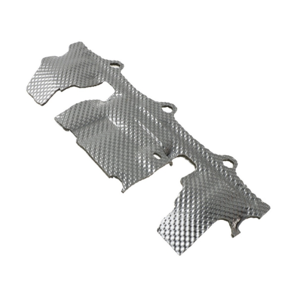
This is especially important for the BSTFLEX stamped exhaust manifold heat shield, where mounting features and the formed shell should be reviewed as one component.
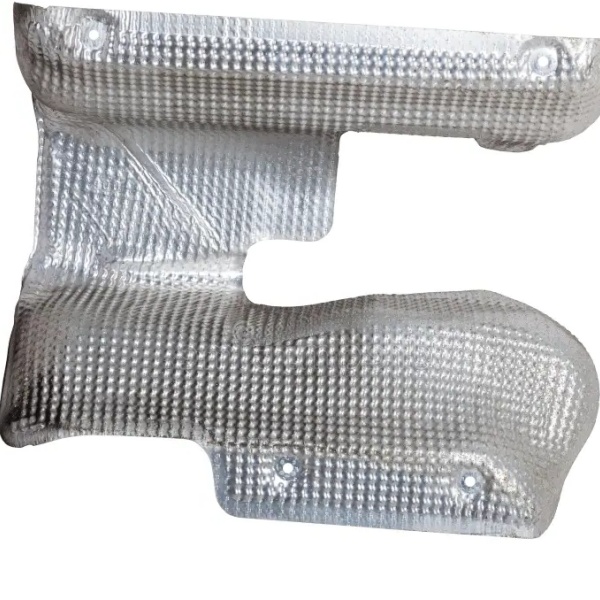
Slots can be useful in a heat shield design, but a slot should not be added simply because a round hole was difficult to assemble during the first trial.
If a drawing uses an elongated hole, define why it exists and which direction of movement or adjustment it is intended to accommodate. The supplier also needs to know which end, centerline or datum controls inspection.
Likewise, increasing every hole diameter to make assembly easier can reduce location control. If a sample requires repeated manual adjustment before the fasteners align, investigate the actual geometry before converting those adjustments into production dimensions.
The heat shield is not a structural brace for the manifold, turbocharger or exhaust pipe. Its mounting points should locate the shield without being used to force the exhaust system into position.
If the manifold, turbocharger connection or support bracket is already misaligned, solve that condition separately. Designing the shield around an incorrectly assembled reference part can reproduce the problem in every production component.
For replacement projects, photograph the original part in its installed position before removal. Record whether the sample is distorted, cracked or previously modified. Do not automatically treat damaged geometry as the intended production shape.
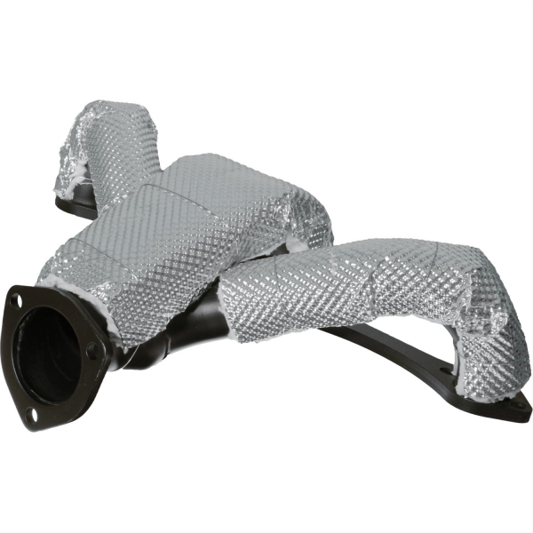
Some metal thermal barriers are designed with a controlled separation from the heat source. Other heat-shield constructions may fit much closer to a component or incorporate insulation within the assembly.
These concepts should not be mixed simply because both products are made from formed metal.
When requesting a quotation, identify whether the requirement is:
BSTFLEX also supplies other exhaust thermal management products outside C27. For a broader comparison of metal shields, blankets, liners and pipe insulation, refer to the exhaust heat shield and insulation guide.
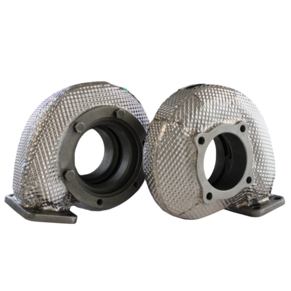
A turbocharger metal heat shield may need to fit around a compact combination of the turbine housing, exhaust inlet, outlet connection, actuator system and oil or coolant lines.
The drawing should show which of these areas must remain accessible. A shield that gives excellent coverage but blocks an actuator linkage, fastener or service connection is not a finished solution.
For the BSTFLEX Stamped Turbocharger Heat Shield, submit the installed turbocharger configuration rather than a turbine housing photograph alone. Mounting and clearance decisions depend on the surrounding assembly.
Where the turbo shield meets a manifold shield, identify the boundary between the two parts. Do not assume overlapping them is always beneficial. The interface can affect clearance, service access and assembly order.
A pipe-mounted shield may use brackets or clamps instead of fixed casting bosses. The installer then needs enough straight pipe length for the hardware and enough surrounding space to position the shield.
Flanges, welds, bends, sensors and flex sections can reduce usable mounting space even when the nominal pipe diameter is correct.
For this type of application, see the BSTFLEX exhaust pipe heat shield kit sizing and mounting guide. It covers pipe diameter, shield orientation and clamp-based installation separately from stamped manifold and turbo shields.
The first sample should be reviewed in the intended assembly, not only on a bench.
A practical installation review can record:
If the sample must be modified to fit, record the modification and update the drawing before repeat production. Do not approve the unmodified drawing while relying on undocumented workshop adjustments.
An air gap should ultimately support a measurable thermal requirement. Define what needs to stay below a specified temperature and where that temperature will be measured.
Possible measurement locations include the protected hose, connector or vehicle panel, the shield outer surface or another project-specific point. These temperatures are not interchangeable.
Record the operating condition, ambient temperature, airflow, duration and measurement method together with the result. Infrared measurements also require appropriate consideration of surface characteristics and instrument setup; comparing readings from different reflective surfaces without a controlled method can be misleading.
A successful result from one installation should not be converted into a universal claim that a particular air gap or sheet material always provides the same temperature reduction.
For a custom stamped metal heat shield, the quotation package should define both the part and its installed environment.
| RFQ item | Recommended information |
|---|---|
| Heat source | Manifold, turbocharger or other component identification and available temperature data |
| Protected component | Part requiring thermal protection and its applicable temperature requirement |
| Shield geometry | Drawing, CAD data, reference sample or dimensioned installation information |
| Material | Required grade and thickness, or state that BSTFLEX may propose a construction |
| Mounting | Attachment points, hardware scope, tabs, brackets, slots and service access |
| Clearance | Critical hot-side and cold-side limits |
| Validation | Fit, dimensional, thermal or application checks required for sample approval |
| Supply | Prototype quantity, production volume, packaging and identification requirements |
Identify which requirements are fixed and which remain open for supplier review. This makes it easier to compare proposals without assuming that two shields with the same external outline are technically equivalent.
The BSTFLEX Metal Stamping Heat Shields category covers rigid formed heat-shield projects for automotive exhaust thermal management.
Current product references include the Exhaust Manifold Heat Shield and Stamped Turbocharger Heat Shield. Final geometry, mounting arrangement, material and validation requirements should be confirmed for the individual project.
Send BSTFLEX your heat shield drawing or sample for review. Include installation photographs or assembly data showing the heat source, mounting points, available clearance and component requiring protection.

No.10, Chuangxin North Road, Nanshan Park, Ningguo Economic and Technological Development Zone, Ningguo City, Anhui Province, China
điện thoại/Whatsapp : 0086-15856303740
e-mail : sales@bstbraidedsleeve.com
Skype : vanesa-cheng