Bạn đang tìm kiếm cái gì?
An aluminum intake heat shield is not effective simply because a reflective panel has been placed somewhere between the exhaust and the air filter. Its performance depends on whether the barrier blocks the relevant radiant path, maintains clearance from hot components, permits the intended airflow and remains stable after engine movement and vibration.
For OEM and custom fabrication projects, the material specification should therefore be developed together with the installed geometry. Alloy, temper and sheet thickness matter, but so do the shield outline, flange direction, mounting points, service access and the location of the intake-air temperature sensor.
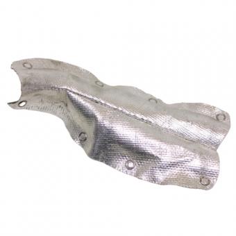
BSTFLEX supplies embossed aluminum heat shield material that can be cut, folded and formed into custom engine-bay barriers. This guide focuses on designing and ordering a rigid aluminum intake shield rather than flexible ducting, hood insulation or adhesive-backed thermal mats.
The phrase intake heat shield can refer to several different components. Before selecting a sheet or developing a blank, identify the part whose temperature or heat exposure needs to be controlled.
A shield designed to protect an exposed filter from a nearby exhaust manifold is different from a panel separating an airbox from a turbocharger. The first may require broad line-of-sight coverage. The second may need a compact formed barrier with carefully controlled clearances and mounting points.
State the protected component and its allowable condition in the project requirement. “Reduce engine-bay heat” is too general to define a production part.
Engine-bay heat can reach the intake system from several directions. Common sources include an exhaust manifold, turbocharger turbine housing, downpipe, catalytic converter section, exhaust crossover or another hot assembly positioned close to the intake route.
Begin with an assembly view showing the heat source, protected component and proposed shield. From the position of the filter, pipe or airbox, check whether any part of the hot surface remains directly visible around the panel.
This line-of-sight review is important because a barrier can cover the center of a heat source while leaving a runner, flange or turbine outlet exposed at the edge. Increasing sheet thickness does not correct incomplete coverage.
Use the first prototype to confirm:
A rigid aluminum barrier is normally most useful when it is spaced from the heat source. Direct contact creates a conductive path and changes the role of the sheet from a separated radiant barrier to a contact layer.
There is no universal air gap that suits every engine bay. The required clearance depends on heat-source temperature, panel size, airflow, mounting arrangement, engine movement and the temperature limit of the protected component.
On the drawing, define the minimum operating clearance rather than only the cold installation gap. Review:
A shield that clears the turbocharger while the vehicle is stationary may contact it under load if movement has not been considered.
Aluminum is attractive for intake-side barriers because it is lightweight, formable and suitable for broad engine-bay panels. The final result still depends on the selected alloy, temper, gauge, surface condition and part geometry.
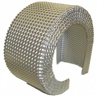
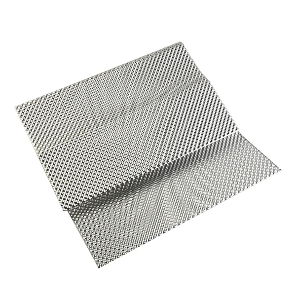
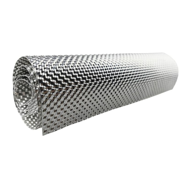
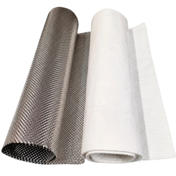
BSTFLEX supplies embossed aluminum sheet for forming into lightweight thermal barriers. The embossed profile increases structural stability compared with a completely flat thin sheet, helping the panel maintain its designed shape after cutting and bending.
For alloy selection, review 1050, 1100, 3003 and 5052 aluminum heat shield materials. Do not approve an alloy substitution from the grade number alone; temper and forming requirements must also be considered.
An intake shield often includes large unsupported areas, curved surfaces or narrow mounting tabs. Thin flat sheet can flex during handling and may require additional beads, folds or brackets to achieve the required stiffness.
An embossed surface introduces three-dimensional geometry into the material. This can help:
Embossing does not replace correct mounting or clearance. It also does not establish a higher temperature limit for the base alloy. The structural role of the pattern is explained further in why automotive heat shields use embossed metal.
An intake barrier should prevent unwanted radiant exposure without unintentionally blocking the air path needed by the intake or engine-bay cooling system.
For an open-filter installation, define where the filter receives air. A panel that surrounds the filter but leaves it drawing only hot engine-bay air may not achieve the intended result. A formed barrier can separate the filter from the hot side of the engine bay while leaving an inlet path toward a cooler air source.
For an enclosed airbox, review whether the metal shield protects the box wall or whether the airbox itself already provides the required separation. Avoid adding a panel that interferes with the inlet duct, drain path, fastening clips or filter replacement.
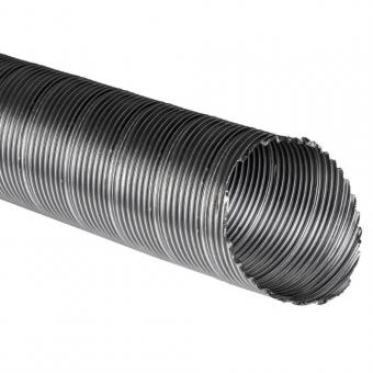
The intake heat shield and the intake duct are different components. Flexible preheater hose, PAP or APK ducting and warm-air routing belong to the heat protection tube and warm air ducting range, not to the rigid p56 sheet-material specification.
A flat plate may be sufficient for an early fit check, but production barriers often need formed edges. Flanges can improve local rigidity, increase coverage and create mounting surfaces.
Common features include:
Every flange changes the flat blank. Define flange height, direction, bend location and finished clearance before the production outline is released.
Do not extend the barrier until it creates a sealed enclosure unless that arrangement has been intentionally designed and validated. A larger shield is not automatically a better shield.
The mounting system influences both mechanical durability and thermal behavior. A bracket attached directly to a hot exhaust component can conduct heat into the shield, while a body-mounted or intake-side support can create a different boundary condition.
Mark each attachment point and its supporting structure on the assembly drawing. Review:
Do not use fasteners to pull a poorly formed panel into position. The free-state shape should be close enough to the installed geometry that assembly does not impose uncontrolled stress on the tabs.
Modern intake systems may include a mass airflow sensor, intake-air temperature sensor or combined sensing module. A shield can protect the housing and connector from radiant exposure, but it should not alter the intended airflow path or make the sensor impossible to service.
When a temperature sensor is used to evaluate the shield, identify whether the test records:
These values answer different questions. A lower shield surface temperature is not proof that the intake air has changed by the same amount.
The shield should be validated against the requirement assigned to it. For example, it may need to reduce radiant exposure to an airbox wall or keep a wiring connector below an agreed temperature.
Claims about engine output, intake density or vehicle performance require a broader test of the complete intake and engine system. They should not be inferred from the use of reflective aluminum sheet alone.
A useful development test records the installation and operating conditions clearly:
| Test Item | Information to Record |
|---|---|
| Operating condition | Vehicle speed or test-cell airflow, engine load, duration and ambient conditions |
| Heat source | Component and measurement location |
| Shield | Material, gauge, geometry, mounting and measured points |
| Protected component | Surface or connector location and acceptance limit |
| Intake data | Sensor location and whether the value represents internal air, component surface or surrounding air |
| Comparison | Same installation and operating cycle with the approved baseline |
Once the installed outline is established, create the flat blank. Include the material needed for bends, edge returns, mounting tabs and any post-forming trim operations.
BSTFLEX currently lists embossed aluminum sheets in 300 × 500 mm, 500 × 500 mm, 500 × 700 mm and 1 m × 1 m formats, with custom sizes available by request. Select the purchased sheet by usable blank yield, not by area alone.
For detailed blank and nesting considerations, see aluminum heat shield sheet sizes for OEM fabrication.
The flat-pattern drawing should identify:
Review the view from the filter, pipe or airbox. If hot components remain visible around the edges, adjust the outline or add a formed return before increasing material thickness.
Measure the minimum operating clearance across expected movement and tolerance. Reposition the panel or mounting system rather than accepting intermittent contact.
Define the air inlet and check the shield in the complete engine-bay assembly. Preserve the required opening area and avoid obstructing ducts, clips or filter service.
Review tab geometry, bend location, edge condition, restraint and vibration. Changing to a thicker sheet without identifying the failure mechanism may move the problem instead of correcting it.
Record the final blank and forming sequence, then reproduce the part from a fresh sheet. A manually corrected sample does not establish a repeatable production process.
A formed intake shield is a localized metal barrier positioned near the intake system. Hood insulation covers a broad bonnet or hood area and can combine thermal and acoustic functions.
These products should not be treated as interchangeable. For under-hood liner or bonnet insulation requirements, use the separate Hood Engine Bay Heat Shield product. For a rigid barrier between the intake and a localized hot source, p56 embossed aluminum sheet is the more relevant material starting point.
A rigid sheet is mounted as a self-supporting or bracket-supported barrier. An adhesive-backed material is bonded to another surface. The two constructions have different installation requirements and should not share one generic specification.
Where a customer needs a bonded liner or peel-and-stick thermal barrier, review the thermal and heat shield barrier range. For a formed air gap barrier, specify the aluminum sheet, blank and mounting features.
| RFQ Field | Information to Provide |
|---|---|
| Protected component | Filter, airbox, intake pipe, sensor, wiring or other component |
| Heat source | Exhaust manifold, turbocharger, downpipe or other source |
| Installation model | Assembly drawing, 3D model, photographs or physical sample |
| Material | Required aluminum alloy and temper, or request for supplier review |
| Base-metal thickness | Specified gauge and tolerance where controlled |
| Embossing | Pattern reference, orientation and any flat zones |
| Shield geometry | Finished outline, flanges, tabs, holes, slots and edge details |
| Clearance | Cold and minimum operating gaps from hot and moving components |
| Supply scope | Sheet, cut blank or formed component |
| Validation | Protected component, measurement locations, duty cycle and acceptance criteria |
| Quantity | Prototype quantity, batch size and estimated annual requirement |
Aluminum is commonly considered for lightweight formed intake barriers because it can be cut and shaped into engine-bay panels. The exact alloy, temper, thickness and geometry should be selected for the installation rather than specified only as aluminum.
A separated barrier generally avoids the direct conductive path created by metal-to-metal contact. The required gap must be established from the heat source, movement, airflow and protected-component limit; there is no single universal dimension.
Not automatically. It should block the relevant hot-side exposure while preserving the intended air inlet, drainage, service access and engine-bay airflow. A complete enclosure requires its own air-supply design.
No. Thickness affects strength and forming, but coverage, mounting, air gap and embossed geometry also control the result. Unnecessary thickness adds weight without correcting an incomplete radiant barrier.
Yes. BSTFLEX embossed aluminum sheet can be cut, folded and shaped for custom barriers. Provide the finished geometry, blank requirements and mounting details so the supply scope can be reviewed correctly.
It can protect more than one component when the geometry blocks the relevant heat paths and maintains safe clearances. Each protected component should still have its own acceptance requirement.
BSTFLEX supports sheet supply and custom heat shield development according to drawings, samples and project requirements. State whether the inquiry is for raw material, a cut blank or a finished formed component.
BSTFLEX supplies embossed aluminum thermal barrier sheet for engine-bay, intake, underbody and other radiant heat protection projects.
Send the engine-bay layout, protected component, heat-source position, required material, blank or finished dimensions and prototype quantity. Include the minimum available clearance and identify any sensor, duct or service-access restrictions.
For hotter or mechanically more demanding shield locations, BSTFLEX can also review embossed stainless steel heat shield material or Alloy 625 Inconel heat shield material as separate material options.
Send your intake heat shield drawing and RFQ to BSTFLEX for material, forming, prototype and OEM production review.

No.10, Chuangxin North Road, Nanshan Park, Ningguo Economic and Technological Development Zone, Ningguo City, Anhui Province, China
điện thoại/Whatsapp : 0086-15856303740
e-mail : sales@bstbraidedsleeve.com
Skype : vanesa-cheng