Bạn đang tìm kiếm cái gì?

An OEM catalytic converter heat shield project usually starts with a simple request: protect a floor panel, wiring harness, fluid line, sensor, transmission component or nearby assembly from converter heat. The part itself may look straightforward, but a reliable production shield depends on geometry, coverage, clearance, material construction, mounting and repeatable installation.
This guide is written for vehicle manufacturers, exhaust-system suppliers, performance brands, replacement-parts companies and distributors preparing a custom heat shield inquiry. It focuses on the information a manufacturer needs before recommending a construction or producing a prototype.
For a general-purpose product, review the BSTFLEX catalytic converter heat shield. For broader product selection, visit Other Heat Shield Products.
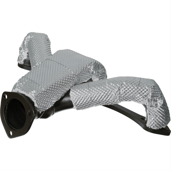
Length, width and circumference are important, but they do not define the complete application. Two converters with similar external dimensions can require different shields because the installation environment is different.
One converter may sit beneath a passenger floor with enough space for a stand-off metal shield. Another may be positioned close to an oil line or wiring harness and require a compact multilayer barrier. A replacement-parts program may need broad fitment, while an OEM program may require a shaped part with fixed holes, brackets and controlled installation orientation.
Before discussing material, identify the thermal problem:
These questions determine whether the project should use a formed metal shield, a flexible multilayer shield, a removable insulation blanket or a hybrid construction.
| RFQ Item | Information to Provide | Why It Matters |
|---|---|---|
| Vehicle or equipment | Vehicle model, engine, exhaust layout, machine type or platform name | Provides application context and helps identify packaging limitations. |
| Converter geometry | Overall length, body width, circumference, inlet and outlet locations, cones, seams and sensor positions | Defines the shield shape and the areas that must remain open. |
| Protected component | Floor panel, wiring, hose, fuel line, brake line, oil system, transmission, plastic part or other assembly | Clarifies the direction in which heat must be controlled. |
| Available clearance | Minimum distance between the converter, shield and neighboring parts | Determines allowable thickness, air gap and fastening method. |
| Thermal condition | Normal operating condition, peak condition, duty cycle and any measured temperatures | Supports material and insulation selection. |
| Environment | Underbody, engine bay, off-road, marine, commercial vehicle, stationary engine or other service condition | Influences corrosion resistance, abrasion protection and outer-surface selection. |
| Mounting method | Existing brackets, studs, holes, clamps, ties, straps, springs or new mounting proposal | Controls installation repeatability and vibration performance. |
| Service requirement | Permanent installation, occasional removal or frequent inspection | Helps determine whether a rigid, flexible or removable construction is appropriate. |
| Quantity | Prototype quantity, first production order and estimated annual usage | Affects tooling, manufacturing route, packaging and unit cost. |
| Documentation | Drawing, inspection report, material declaration, labeling, traceability or packaging requirements | Allows the supplier to quote the complete program rather than only the physical part. |
A formed metal shield is often selected when the part needs a defined shape, stable mounting points and a controlled air gap. Depending on the project, it can be made from aluminum, stainless steel or a higher-performance alloy. Embossing, ribs, folds and formed edges can improve stiffness without relying only on thicker material.
This construction is suitable when:
A formed shield should not be specified by alloy alone. The drawing should also define material thickness, embossing or rib pattern, formed height, hole location, edge condition, mounting interface and any insulation layer attached to the metal shell.
A flexible multilayer heat shield can follow a range of converter shapes without requiring a fully stamped shell. It may combine a metallic or aluminized outer surface, an insulation layer and a heat-resistant inner construction. Stainless steel ties, clamps or other mechanical retention can hold the shield in position.
This approach is useful for:
Flexible does not mean undefined. The finished part still needs controlled dimensions, reinforced openings, secure edge finishing and a fastening layout that prevents movement toward sensors, welds or adjacent components.
A removable blanket places more insulation close to the heat source and can be shaped around an irregular housing. It may be appropriate where localized heat containment is required and where the blanket must be removed for service.
Review the Thermal Insulation Catalytic Converter Heat Blanket for this construction type.
The decision to insulate a catalytic converter closely should be made against the actual exhaust-system design. Coverage, ventilation, sensor locations, converter durability and the vehicle manufacturer's thermal requirements must be considered. A blanket should not be treated as a universal substitute for every original metal shield.
A hybrid shield combines a formed or semi-rigid metal surface with an insulation layer. The metal provides shape, environmental protection and mounting stability, while the insulation reduces heat transfer through the assembly.
This format is useful when a thin single metal layer does not provide enough thermal control, but a thick textile blanket would consume too much space or would not meet the mounting requirement.
A catalytic converter heat shield does not automatically need to cover the entire converter. In many systems, the priority is to interrupt the radiation path toward a specific component. Directional coverage can protect the vehicle floor, oil system, electrical harness or fluid line while leaving other areas open.
Coverage should be defined on the drawing or marked on photographs. Identify:
For a vehicle-specific example, see the 2014–2019 Corvette C7 Catalytic Converter Heat Shield. A model-specific project requires different dimensional control from a broadly compatible universal shield.
It is more useful to assign a function to each layer than to request one material name for the entire part. A multilayer heat shield may need separate materials for the hot face, insulation core, outer surface, edge reinforcement and fasteners.
| Part of the Shield | Typical Material Options | Selection Factors |
|---|---|---|
| Rigid outer shell | Aluminum, embossed aluminum, stainless steel, embossed stainless steel, nickel alloy | Weight, corrosion exposure, stiffness, forming method, service temperature and cost. |
| Reflective outer surface | Aluminum foil, aluminized fabric or metallic laminate | Radiant-heat direction, environmental exposure, flexibility and surface durability. |
| Insulation layer | Fiberglass, high-silica fiber or other high-temperature insulation | Required thickness, compression, thermal exposure, flexibility and handling. |
| Hot-face layer | Stainless steel mesh, heat-resistant textile or metal facing | Direct exposure, abrasion, contamination and attachment to the insulation package. |
| Edge and opening reinforcement | Folded metal edge, sewn high-temperature tape, grommet, eyelet or reinforced patch | Cut resistance, installation load and repeated service. |
| Fastening system | Stainless steel ties, clamps, straps, springs, bolts, studs or brackets | Vibration, installation time, removal requirement and available mounting points. |
Temperature capability is only one part of the decision. The material also has to survive thermal cycling, vibration, moisture, road contamination and the forces introduced during installation.
A stand-off heat shield normally relies on a controlled space between the hot component and the shield. That space interrupts direct conduction and can improve the performance of a reflective metal barrier. The mounting design must maintain the gap after repeated heating, cooling and vibration.
A contact or close-fitting flexible shield works differently. It uses insulation to slow heat transfer and may wrap around part of the converter body. The construction must remain stable without sliding, opening at the seam or concentrating load on sensors and wiring.
The RFQ should state whether the proposed shield is:
Without this information, quotations based on the same external dimensions may describe entirely different products.
Many heat shield problems begin at the mounting interface rather than in the insulation material. A shield that moves, rattles or rotates can lose coverage and contact nearby components.
Review the following points during design:
For a replacement-parts program, the installation method should be understandable without factory tooling. For an OEM assembly line, the priority may be takt time, poka-yoke features, controlled fastener torque and consistent part orientation.
BSTFLEX can review projects from a customer drawing, CAD geometry, dimensional sketch, marked photographs or a customer-owned physical sample. The best starting format depends on the maturity of the project.
A controlled drawing is the preferred basis for repeat production. It should identify critical dimensions, datums, hole locations, material stack, thickness, tolerances, edge treatment and revision level.
CAD data is useful for shaped metal shields and tightly packaged assemblies. Include surrounding components or a clearance envelope when possible. A converter model alone does not show the floor, wiring, brackets and other parts that define the available space.
A sample can establish the basic geometry, but it should be accompanied by application information. A used part may be distorted, contaminated or altered by service. The project should distinguish between dimensions copied from the sample and dimensions that must be corrected for production.
For early evaluation, provide photographs from several angles with a scale or dimension reference. Mark the heat source, the protected part, proposed mounting points and restricted zones. This method can support an initial recommendation, but a controlled drawing or approved sample is still needed before repeat production.
For more information about available processing and packaging support, see BSTFLEX Custom Capabilities.
A prototype should answer more than the question, “Does it fit?” The sample review should confirm whether the part can be installed consistently and whether it remains in the intended position during operation.
A practical approval plan may include:
Thermal performance should be evaluated in the installed assembly. Material datasheets are useful for screening, but they do not replace measurements on the actual vehicle or exhaust system.
| Inspection Area | Typical Control Method |
|---|---|
| Overall dimensions | Check against the approved drawing, template or inspection fixture. |
| Critical holes and cut-outs | Verify position, size and orientation against defined datums. |
| Material construction | Confirm alloy, textile, insulation, layer sequence and approved thickness. |
| Formed shape | Use a checking fixture, mating sample or defined profile dimensions. |
| Edge finishing | Inspect folds, bindings, seams and sharp-edge control. |
| Fasteners | Confirm type, quantity, length, attachment and included installation hardware. |
| Workmanship | Inspect for tears, loose fibers, open seams, delamination, distortion and contamination. |
| Identification | Verify part number, revision, batch marking and label position where required. |
| Packaging | Confirm part separation, deformation protection, counted quantity and customer labeling. |
Acceptance limits should be agreed before production. Terms such as “close fit” or “same as sample” are not sufficient for critical dimensions. The approved drawing, golden sample and inspection method should identify what can vary and what must remain controlled.
The commercial format affects the product design and packaging.
OEM programs normally require controlled drawings, revision management, stable materials, repeatable inspection and production packaging. Annual usage and launch timing should be included at the quotation stage.
Aftermarket programs may require broader dimensional tolerance, installation hardware, fitting instructions and retail packaging. The supplier needs to know whether the product is vehicle-specific or intended to fit a range of converters.
Performance applications often have modified exhaust layouts and limited clearance. Flexible or low-tooling constructions may be useful during development, by a more controlled design once fitment is confirmed.
Distributors may require custom labels, neutral packaging, barcode information, instruction sheets and package quantities suited to warehouse handling. These requirements should be quoted with the part rather than added after sample approval.
Send the following information to obtain a more accurate quotation:
When the design is not yet fixed, send the application data rather than selecting a material only by temperature rating. BSTFLEX can compare rigid, flexible and insulated constructions against the available space and production requirement.
Send the application, converter dimensions or drawing, surrounding clearance, protected components, thermal condition, required coverage, mounting method, prototype quantity and production forecast. Photographs with marked hot zones and restricted areas are also useful.
Yes. A customer-owned sample can be used as a development reference. The sample should be accompanied by fitment information and any dimensions that must be corrected or controlled. An approved drawing or golden sample should be established before repeat production.
A universal shield is designed to accommodate a range of converter dimensions and is normally adjusted during installation. An OEM heat shield is developed around a defined vehicle or exhaust assembly and uses controlled geometry, mounting points and production specifications.
Not necessarily. Coverage should follow the thermal objective. A directional shield may protect the floor, wiring or fluid lines without enclosing the complete converter. Full or close coverage requires review of the converter, sensors, ventilation and exhaust-system requirements.
There is no single material for every project. Aluminum can reduce weight, stainless steel offers strength and environmental durability, and multilayer structures can add insulation. The correct choice depends on temperature, clearance, mounting, vibration, corrosion exposure and production method.
BSTFLEX supports rigid metal shields, flexible multilayer shields, insulation-backed constructions and removable catalytic converter blankets. The recommended format depends on the geometry, available space, service requirement and order volume.
Prototype and sample quantities can be reviewed before repeat production. The sample stage should confirm fit, coverage, installation, mounting retention and thermal performance in the actual assembly.
Yes. Labeling, neutral packaging, branded packaging, counted packs, barcodes and customer part-number identification can be reviewed as part of an OEM or distributor program.
Ningguo BST Thermal Products Co., Ltd. manufactures automotive thermal protection products for OEM, aftermarket and private label programs. Projects can be reviewed from drawings, CAD data, dimensions, photographs or customer-owned samples.
Send your project information to contact BSTFLEX. Include the converter geometry, protected components, available clearance, mounting preference, sample quantity and estimated production volume so the construction and quotation can be evaluated together.
thẻ :

No.10, Chuangxin North Road, Nanshan Park, Ningguo Economic and Technological Development Zone, Ningguo City, Anhui Province, China
điện thoại/Whatsapp : 0086-15856303740
e-mail : sales@bstbraidedsleeve.com
Skype : vanesa-cheng